ARTEFACT STUDIES
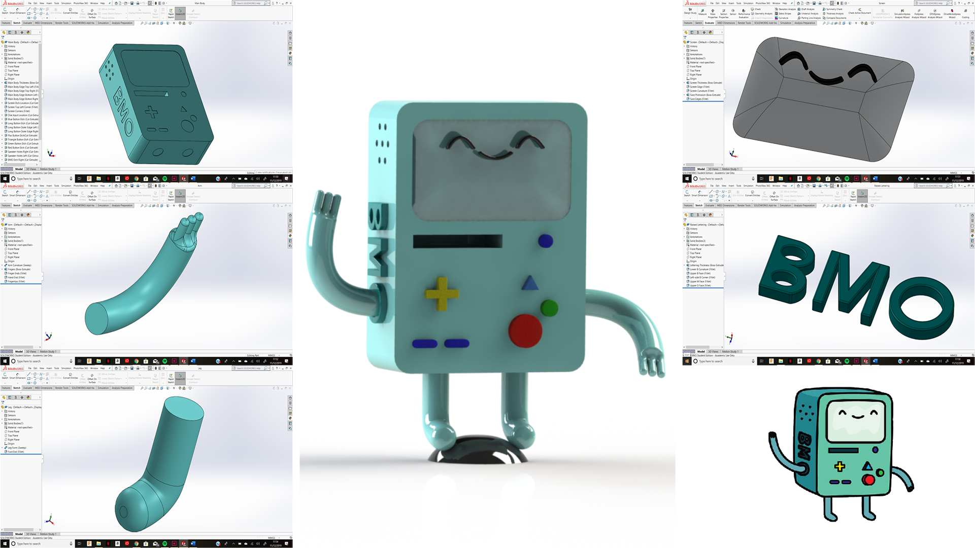
To create this artefact, I began by doing the basic outline of the body, coping the form from a reference image of BMO I found online. I then continued by firstly etching the location for the screen on the model. Once the correct proportions had been worked out, I then created a new separate part file on SolidWorks and formed the screen. I then continued with this method of designing for the rest of the details that were attached to the main body such as the buttons and BMO lettering.
For larger parts such as the arms and legs a lot more calculation was needed in order to ensure the proportions in comparison to the body were correct. I started off by creating a path profile to ensure the correct length and shape and then using the sweep tool to get the correct thickness for the arm/leg. Once this basic form was complete, I then implemented the part into the final assembly to ensure the size and proportions of the arms/legs were not off. Once this was confirmed I then went back to the part file and added in the additional features needed to define what the parts were (fingers for the arm and filleted ends to form the feet.). I then duplicated the final models I created for the arms and legs so that there as two copes (one for each limb) and then rotated, mated and placed them within the assembly accordingly.
To finally render this figurine, I decided to give it a mainly glossy plastic effect as generally toys are formed from this type of material. To give the arms and legs more definition I used a high gloss plastic and then toned down the main body by using a medium gloss plastic effect.
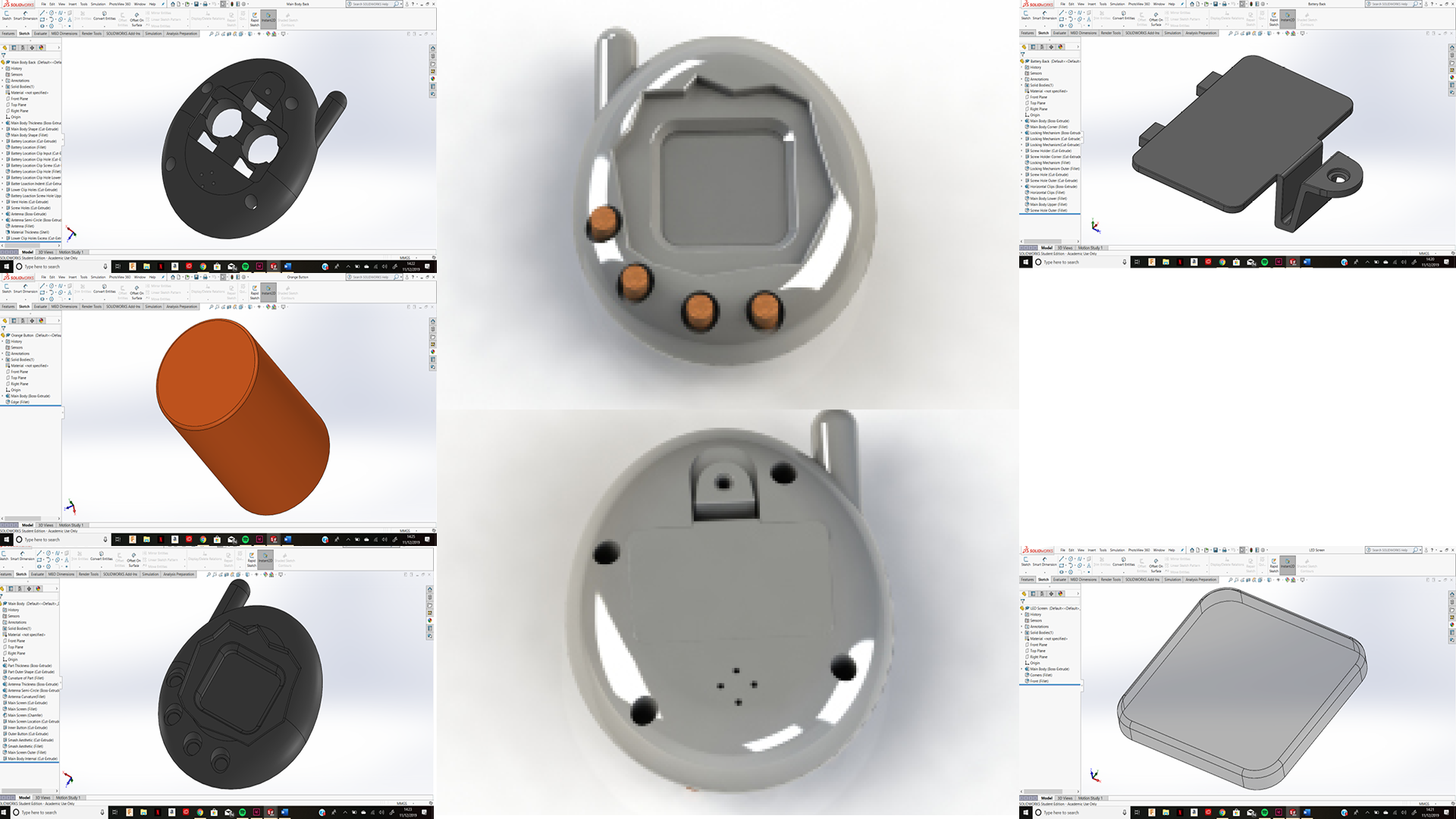
I started off creating this product by firstly taking the physical model apart and seeing how it was manufactured and out together (this would then give me an idea on how the original designer may have done their initial CAD of the product as I can see each individual component with greater detail. I then got out the veneer callipers and took the vital measurements needed to gather a basis for the main form of the product. Once I had this and had sketched out a quick plan as to how I would form the model on SolidWorks I began my model making process. I started off by firstly trying to recreate the front half of the model which contained the screen and buttons. I etched in all the details using the extrude cut tool. After I was happy with the location for all the details, I then hollowed out the interior using the shell tool. I then used this method to create the other half of the main mould for the back of the toy.
As the etching of the parts allowed for me to see where they would be located, I could then easily replicate the screen, buttons and battery casing that would be placed on the toy. For the buttons I simply made one replica and duplicated it when creating the final assemble to help ensure repetition and accuracy. The main challenge when creating this part was aligning the screw hole on the back of the product for the fastening of the battery cover with the location for the input of this. This is because human error when measuring can often occur which meant I had to go back and alter some measurements to ensure perfect alignment one the product was fully assembled.
For the final look of the product I mimicked the original through adding a rubber effect to the buttons and a glossy plastic casing to the exterior casing of the toy.
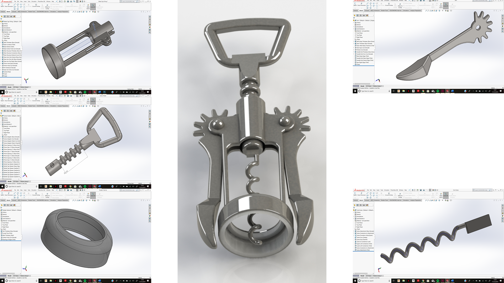
I began creating my mechanism by firstly working on the base of the wine bottle neck holder. After forming the cylindrical shape and extruding it upwards I then filleted and then shelled the shape to create the desired form. This then formed a new flat surface on top of the part I had just created so I simply created a new sketch and extruded upwards from there. The largest challenge when creating this part in preparation for the final assembly was the distance of the holes from the central channel that allowed the pinion gear to travel through. Although I used a veneer calliper to help ensure accuracy of my measurements, human error in the placement of the tool meant I was required to go back and alter the measurements to ensure parts touched and aligned correctly.
The same issue occurred when I also tried to form the arms of the gearing for the arms of the part. This is because I had to ensure that the reach of the gear was long enough to reach the pinion gear in the centre which would then form the mechanism. As well as the gear reach, I also had to ensure that the number of teeth on the gear correlated with the number of teeth on the pinion to ensure that they mesh correctly.
When finally assembling this mechanism, I started off by placing the bottle neck holder in first. I then mated on one side the arm and pin that goes through it. After this I then created a central plane within the bottle neck holder part and mirrored the pin and arm gear onto the other side. This then meant that they also moved in unison, exactly like how the mechanism works in real life. After this I then placed constraints on how far the central screw pinion gear could move and then added a mechanical mate to both this and the arms so that the motions were linked together. This created then completed my mechanism.
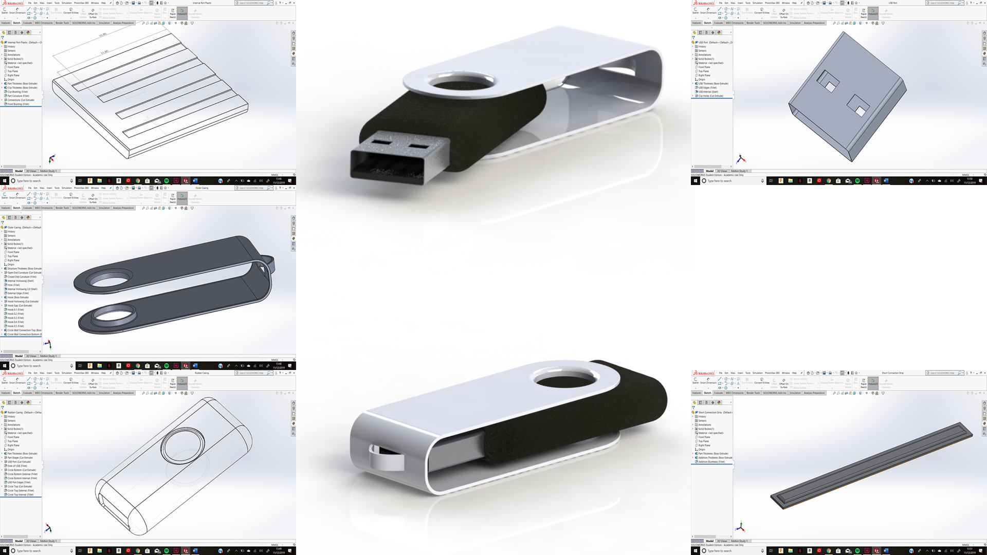
I began the process of recreating this artefact by firstly taking the main measurements for the artefact using the veneer callipers and then doing a quick rough sketch to gather my bearing on how to create the form. I then started to create the main form which was the black casing that surrounded the USB port and protected the internal memory hardware. I measure then diameter of the circle that would be used as the pivot for the outer metallic casing and etched in the outline as well as the location for the USB port.
Now that I had the basis of where the addition parts would be located with the main body, I began to recreate these also. I created the outer metallic shell by firstly extruding the general shape of the USB and then rounding off the edge using a fillet tool. I then filleted the closed off end also and then shelled out the interior. I then replicated the circular pivot location I had placed on the main body of the USB and extrude cut a circle through the metallic exterior. A wall was formed after this that would sit on the interior of the shelled component and sit within the grove created in the previous component, to form the pivot mechanism.
To create the USB port, I made sure I took as precise measurements as I could manage using the veneer callipers, trying to get the reading as close to ISO standards as possible. I measured the interior components of the USB port such as the metallic strips as well as the exterior main structure to try and get it as accurate as possible.
After forming all of the individual parts I then formed the final product as a whole through creating a new assembly and implementing all of the individual parts, mating then accordingly.
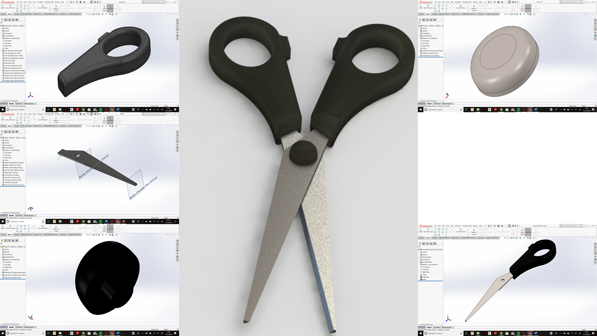
To create this artefact, I began by separating each of the individual parts of the artefact and visualising how I would reassemble them through sketching out a rough plan within my sketch book. To ensure my measurements of the hand-held item were as accurate as possible I used a veneer calliper. The object was split into the following parts: Fingerholes, Blade, Black pin (front view of pin) and silver pin (back view of pin). After creating each of the individual parts I would then create an assembly and reassemble them together using the ‘mate’ tool to form the final CAD design. Once this was complete, I would then carry on to rendering each of the individual parts of the assembly through PhotoView 360, applying a glossy rubber effect to the ergonomic touchpoints of the design and then a brushed steel effect to the scissors blade.
With each individual part came individual challenges. The first part I worked on was the grip that surrounds the fingerholes on the scissors. I began this through sketching the finger hole individually and then offsetting the outside of it to create the exterior material thickness. I then created a tangent line off this and measured to ensure I had the correct overall length of the part. To create the curved organic form, I made use of the ‘fillet’ tool.
The next and most challenging part I worked on was the blade of the scissors. The reason for this was it took me a while to figure out how to recreate the chamfered edge as it starts midbody within the part. In order to do this, I had to implement a new plane along the line where I wanted the chamfer to begin and then split the part into multi-bodies. This then allowed me to select the desired length for the chamfer with ease. After creating the chamfer, I then merged the bodies back together and then filleted the end of the chamfer to create a smoother transition for the blade.
Finally, the last part I formed was the central pin that held the two sides of the scissors together. I did this in two section to make it slightly easier for me in the end when wanting to render the part as one side was brushed steel and the other glossed rubber.
The assembly of the scissors was done by firstly assembling one blade and one rubber fingerhole section and mating them together. I then implemented this assembly into a new one and duplicated the side and flipped it to get the two halves of the scissors.